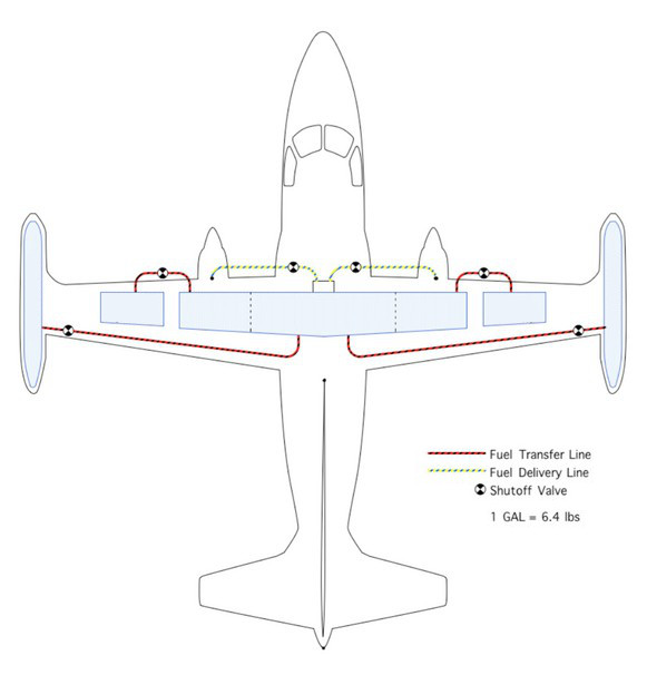
Fuel System Description
The fuel system consists of five individual fuel tanks. The main fuel tank, which is located in the wing above the cabin contains three integral bays. Outboard of the main tank, on each side, are left and right outer wing tanks and on the end of the wings, tip tanks. Fuel is fed to the engines from the main tank only. Fuel is transferred to the main tank from the tips and outer tanks to keep the main tank full. The tank layout is illustrated below along with a table of each tank's usable fuel quantities.

| Left Tip | Left Outer | Main Tank | Right Outer | Right Tip | |
|---|---|---|---|---|---|
| US Gallons | 90 | 34.5 | 154 | 34.5 | 90 |
| Pounds | 607 | 233 | 1040 | 233 | 607 |
| kilograms | 275 | 106 | 453 | 106 | 275 |
Fuel Transfer System
The fuel transfer system is fully automatic and designed to keep the main tank full. As fuel is consumed from the main center tank, fuel is first transferred to the main tank from the tip-tanks via pressurized air tapped from the engines. When the tip tanks are empty, a relay is automatically energized to turn on the outer tank fuel pumps and fuel from the outer wing tanks are then transferred to the main tank. When the outer wing tanks are empty, annunciators on the panel will illuminate to indicate so and the only remaining fuel will be in the main tank. Fuel will not be transferred from the tip tanks and outer tanks simultaneously.
This system is designed to drain the tip tanks first to avoid excess fuel weight in the tip tanks during landings, which can stress the wing structure in a hard landing. When there is 90lbs of fuel remaining in the main tank or less, the "fuel low" annunciator on the annunciator panel will illuminate, warning you of a low-fuel condition and trigger the master caution annunciator on the dash. If this happens, start looking for a place to land, you have about 10 minutes of fuel left!
Fuel System Indicators
There are three fuel gauges along the bottom of the Engine Instrument Panel, just above the quadrant. The left most gauge indicates the fuel in the main tank. The middle gauge indicates fuel in the outers and the right most gauge indicates fuel in the tips. Note that the main fuel quantity indicator is powered by the 115V AC bus whereas the main and tips fuel quantity indicators are powered by DC buses. If the inverter is not on, then there will be no indication of fuel in the main tank fuel.

Fuel System Controls

The controls for the fuel system are found on the right side of the pilot switch panel as shown below. The top two switches energize a relay that opens and closes the Main Fuel Shutoff Valves. These switches are normally switched ON before engine start and switched OFF after shutdown (via the RCS switches).
The bottom two switches control the fuel transfer mode for each engine. When the transfer switches are in the AUTO position, fuel will be transferred automatically as described above. This is the normal operation.
When the switches are in the OFF position, no fuel will be transferred to the main tank. The fuel in the main tank is all you get.
When the switches are in the MANUAL position, fuel will be transferred from the tip tanks only until empty and the outer tanks will NOT transfer fuel to the main tank after the tips run dry. In order to transfer fuel from the outer tanks to the main tank when the transfer switch is not in the AUTO position, you must manually activate the electric outer fuel pumps as described below.
Manual Outer Pump Switch
In the event of a failure of the automatic transfer switchgear in some capacity, or fuel needs to be transferred from the outer tanks to the main for some reason, then the outer tank electric fuel pump may be actuated manually via the manual outer pump switch shown below.

You can verify operation of fuel transfer by observing the fuel gauge needles. This alternate method of fuel transfer from the outer wing tanks exists as a redundant fuel transfer system in the case of a failure of the automatic system.