Anti Ice and De-Ice Systems
The MU-2 has a full compliment of anti-ice / de-ice capabilities. Both electrically heated surfaces and inflatable rubber boots are utilized.
De-Ice System Controls & Indicators
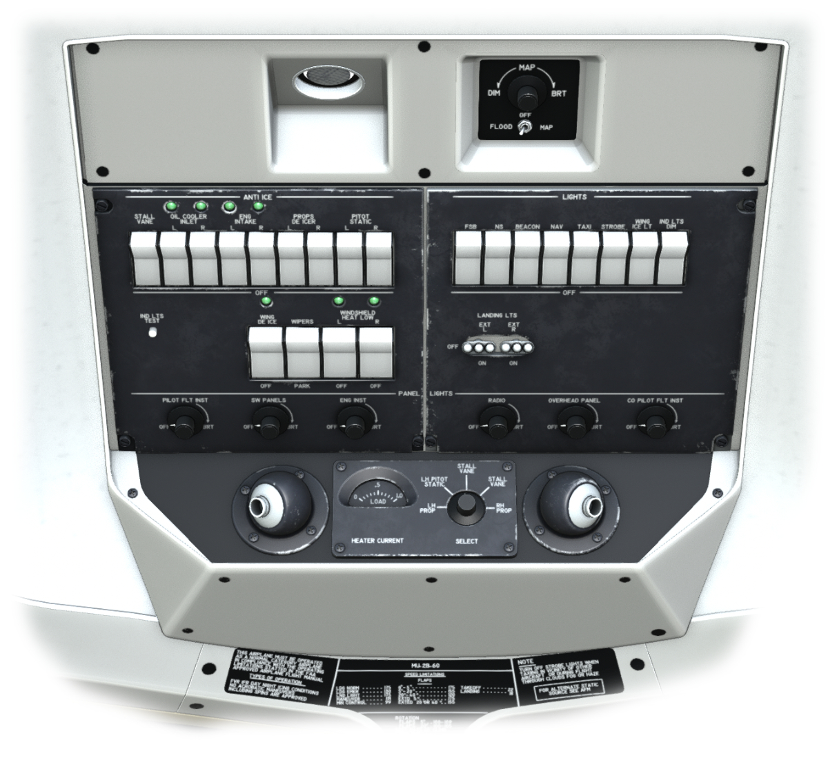
Anti-ice and De-ice controls are located on the overhead. Backlit, circuit-breaker type switches on the left side of the overhead control the anti-ice/de-ice functions. When a switch is moved to ON, it will illuminate. Green status lights will also illuminate to indicate active heating for some systems. (See illustration below) On the lower portion of the overhead is a HEATER CURRENT meter. This meter indicates the relative electrical load on the prop, stall vane and pitot/static system, depending on which system the adjacent is set to display.
Wing De-Icing
Deicing of the wing and empennage is accomplished using bleed air from the engines to periodically inflate and deflates rubber boots on the leading edge of those surfaces. An indicator light, located adjacent to the WING DE-ICE Switch, will illuminate during inflation of the boots and extinguish when the boots have deflated. A wing-ice light is available to visually inspect the wing.
Engine Air Intake Anti-Icing
The engine air intake anti-icing system utilizes hot engine bleed air. Placing the ENG INTAKE switches located on the LH overhead panel to ON, opens a shutoff valve and directs bleed air to the engine inlet. Decreasing torque and increasing EGT verify operation of the system. Two indicator lights, adjacent to the switches, illuminate when the switches are ON.
OIL COOLER AIR INTAKE Anti-icing
The oil cooler air inlet is lined with a rubber boot with electrical heating elements to prevent ice build-up during icing conditions. Placing the OIL COOLER INLET switches, located on the LH overhead switch panel, to ON supplies electrical power to the heating elements of the boots. A load increase on the voltammeters verifies operation of the system. Two indicator lights, adjacent to the switches, illuminate when the switches are ON.
Propeller Anti-Icing
Propeller anti-icing is accomplished using electrical heating elements embedded in rubber boots on the leading edge of each blade. This system is controlled by the PROP DE-ICER switches on the LH overhead switch panel. Verify system operation by setting the HEATER Current Select switch on the overhead panel to the desired Propeller (LH/RH) and check load-meter readings.
Static, pitot and stall warning anti-icing
Pitot tubes, static ports, and stall warning anti-icing is accomplished using embedded electrical heaters. The pitot tubes and static ports heat is controlled by the PITOT & STATIC switches on the LH overhead panel. The stall vane heat is controlled by the STALL switch on the LH overhead switch panel. Verify system operation by setting the HEATER Current Select switch on the overhead panel to the desired device and check load-meter readings.
Windshield Heating
The windshield is heated electrically and consists of an inner and outer tempered glass ply with a vinyl ply sandwiched between them. An electric heating mat is located between the vinyl and outer glass plies. Power is supplied to the heating elements located on the outboard edges of the windshield. Sensing elements are located in the inboard edge of the heating element area to maintain heating within a safe range.
NOTE: X-Plane does not simulate per side heating of the windshield in XPlane 11. As such, the windshield heat switches on the overhead move together as one.
